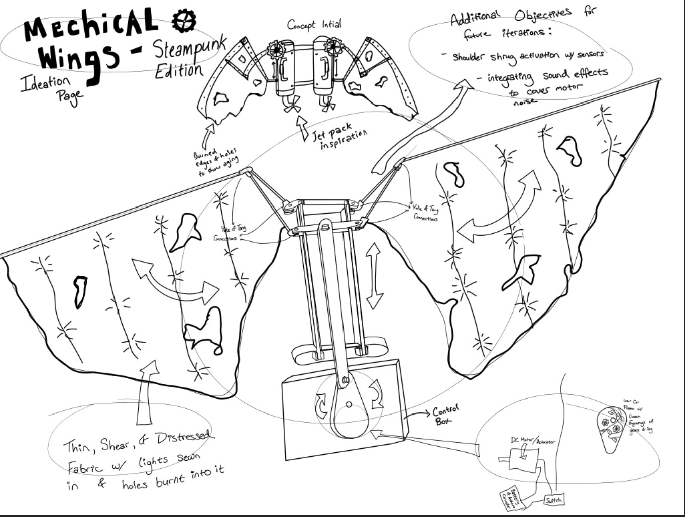
My inspiration drawing that evolved into a full scale project with many redesigns and so many improvements is pictured at the top of the ideation page to the left. The initial plan was to use DC motors on each shoulder to rotate the linkages into place. Eventually, in the spirit of sticking to theme of steampunk and grimy engine pieces, I landed on the following design pictured in the center of the ideation page. A rotating wheel driven by a DC Motor would sit in the middle of the back piece driving a linear motion linkage system up and down. This allowed both wings to be in sync and reduced the need for an additional DC Motor reducing overall cost and the potential for the wings to be out of sync by any number of cycles. The default position for the wings when the power is off will be in the folded position. I will achieve these position specifications through coding of the PI controller and motor. The links will be made of aluminum hollow tubes and the yokes will be 3D printed. All of this will create a light weight frame work that can be carried on ones back. Future iterations may include experimentation into activation via sensors triggered by the wearers specific movements instead of a switch.
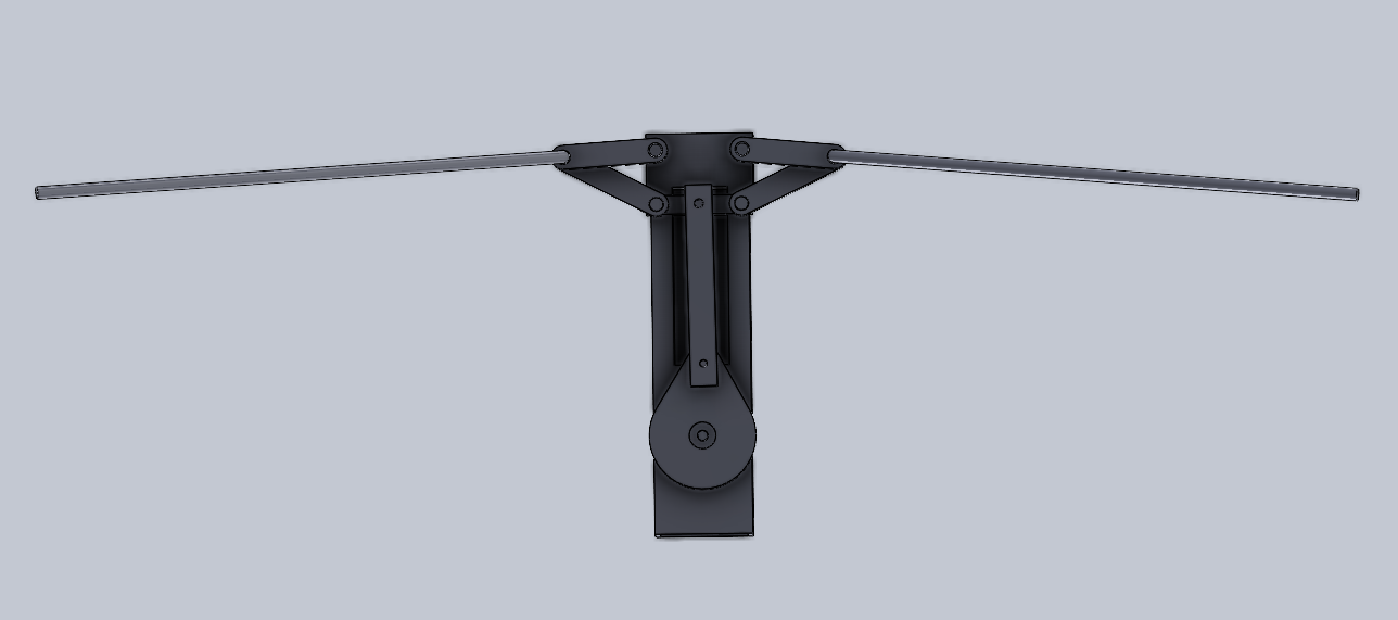
The following is an animation depicting the linkages in motion and fully measured out.
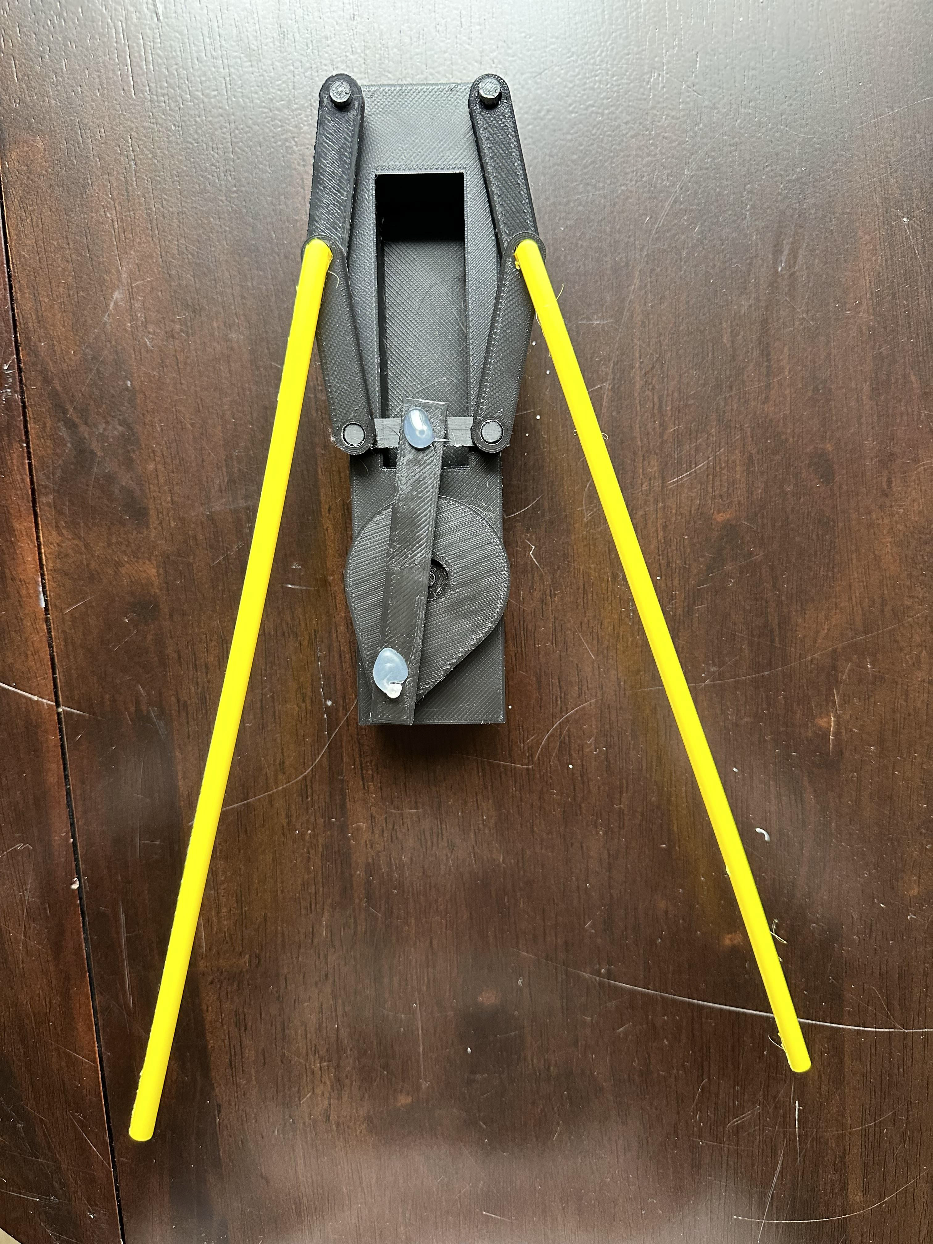
Below is a 3D model made in Solidworks depicting the basic proof of concept. This model is currently being 3D printed as a 1/3rd scale model. My next steps in the next months are to hook the scale model to an Arduino motor and finish a second prototype with greater detailed parts. The next model, I will analyze with the appropriate loads to determine beam bending and the minimum torque required in order to size the motor.
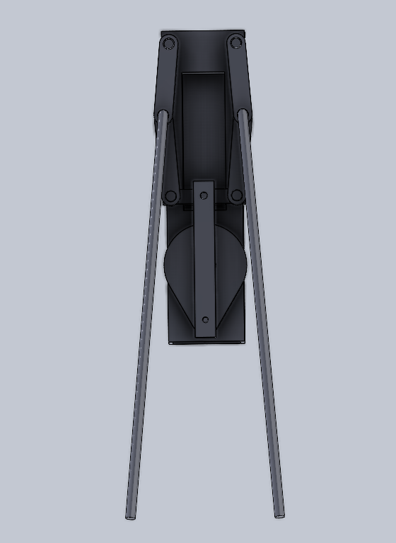
3D-Printed 1/3rd Scale Model Proof of Concept: