Design Requirements and Restrictions:
- Must fit through a standard doorway (~34")
- Deflection at any point must be less than 0.5"
- Must be pushed by a person from behind, but steered by operator
- Prototype must be constructed from PVC pipes and fittings
- Must have good maneuverability with stability at higher speeds
- Low center of gravity to avoid rolling
- Survive multiple crashes with other similarly sized and weighted objects
- Frontal and lateral crashes, emphasis on lateral support
Driver Profile Constraints:
- Height: 6' 0"
- Weight: 155 lbs
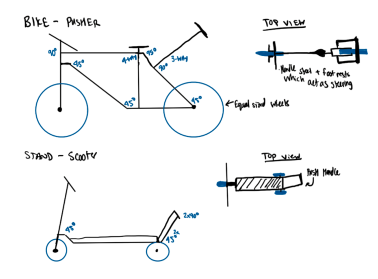
Initial Designs:
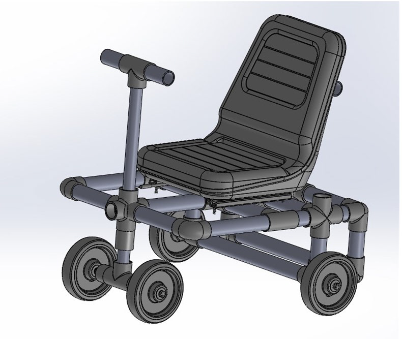
The left most design, was the design chosen to explore.
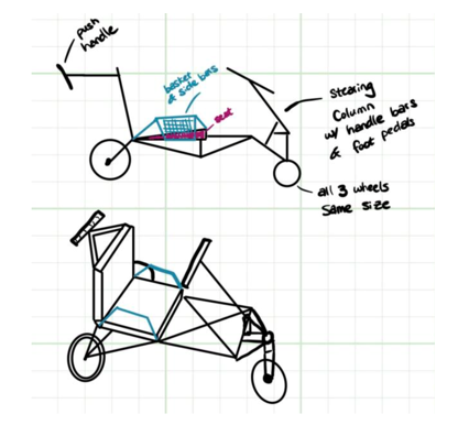
As with any good design, we needed a backstory and inspiration for our design:
This is meant to be ridden on a crazy Black Friday shopping trip. It should be able to make sharp turns to go down isles and be able to take hits from the side from other crazy shoppers. It should be able to go over miscellaneous goods that have fallen off the shelf and possibly other shoppers if need be. We want it to be able to go relatively fast but mostly make sure it is sturdy, so the driver does not get launched out of the cart. This would cut into valuable shopping time. We also want it to include a side basket to be able to put all kinds of amazing findings in and include steering you can control with your feet so you can use your hands to get goods off the shelves.
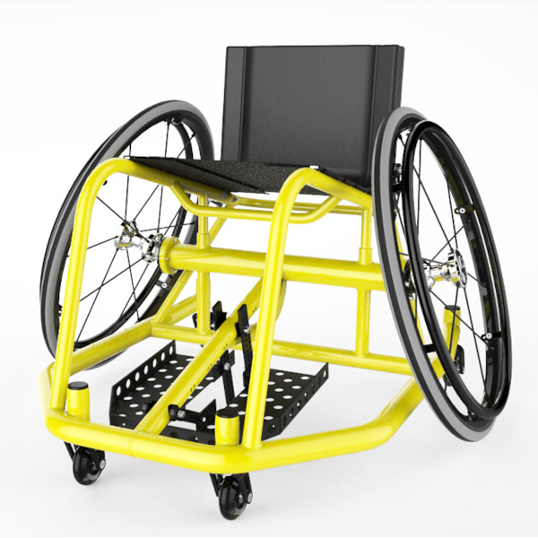
Real Life Inspiration:
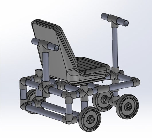
We used inspiration for the truss and cage like protective design from rugby wheelchairs. Rugby wheelchairs are known for their stability and maneuverability. While we did not incorporate the large wheel design for steering and stability, we utilized a similar frame structure as a few rugby wheelchair models which included protective frames surrounding the chair to protect the user from harsh collisions.
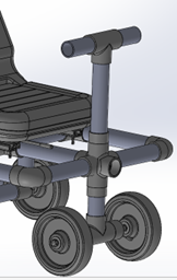
3D Solidworks Model and Generalized Materials:
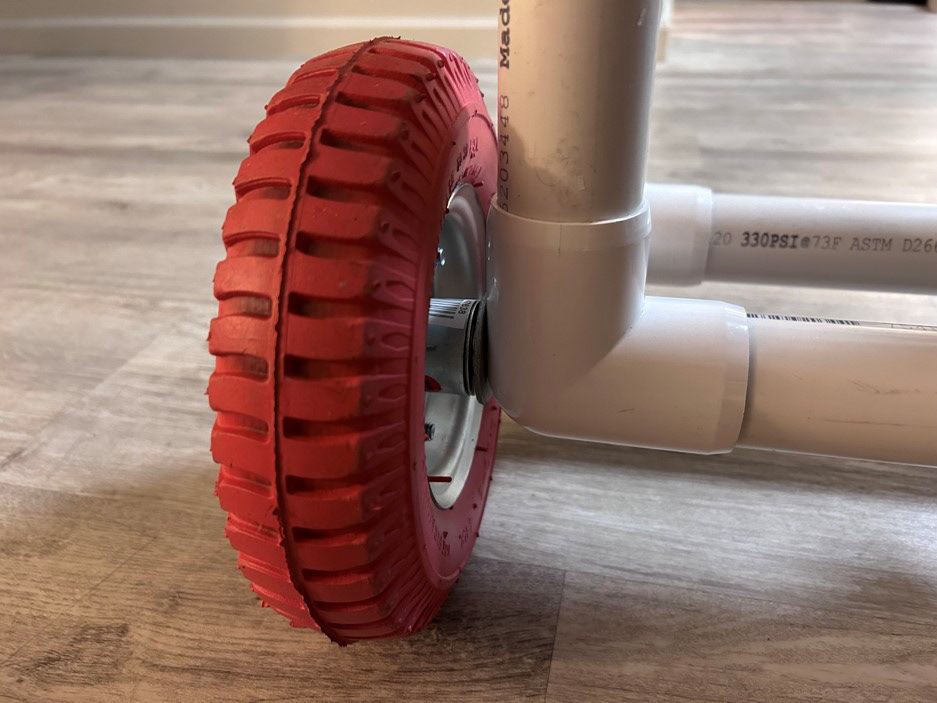
- 1/2 in PVC piping
- 5/8" Steel Rod Axles
- 8" Wheels to traverse bumpy terrain
FEA Analysis Using Solidworks Simulation:
- 3 load cases on the frame were analyzed.
1) Load normal to the cart seat in the vertical plane
2) Load Normal to the Back Handle bars in the horizontal plane
3) Combining 1) and 2) to simulate a person seated on cart while being pushed
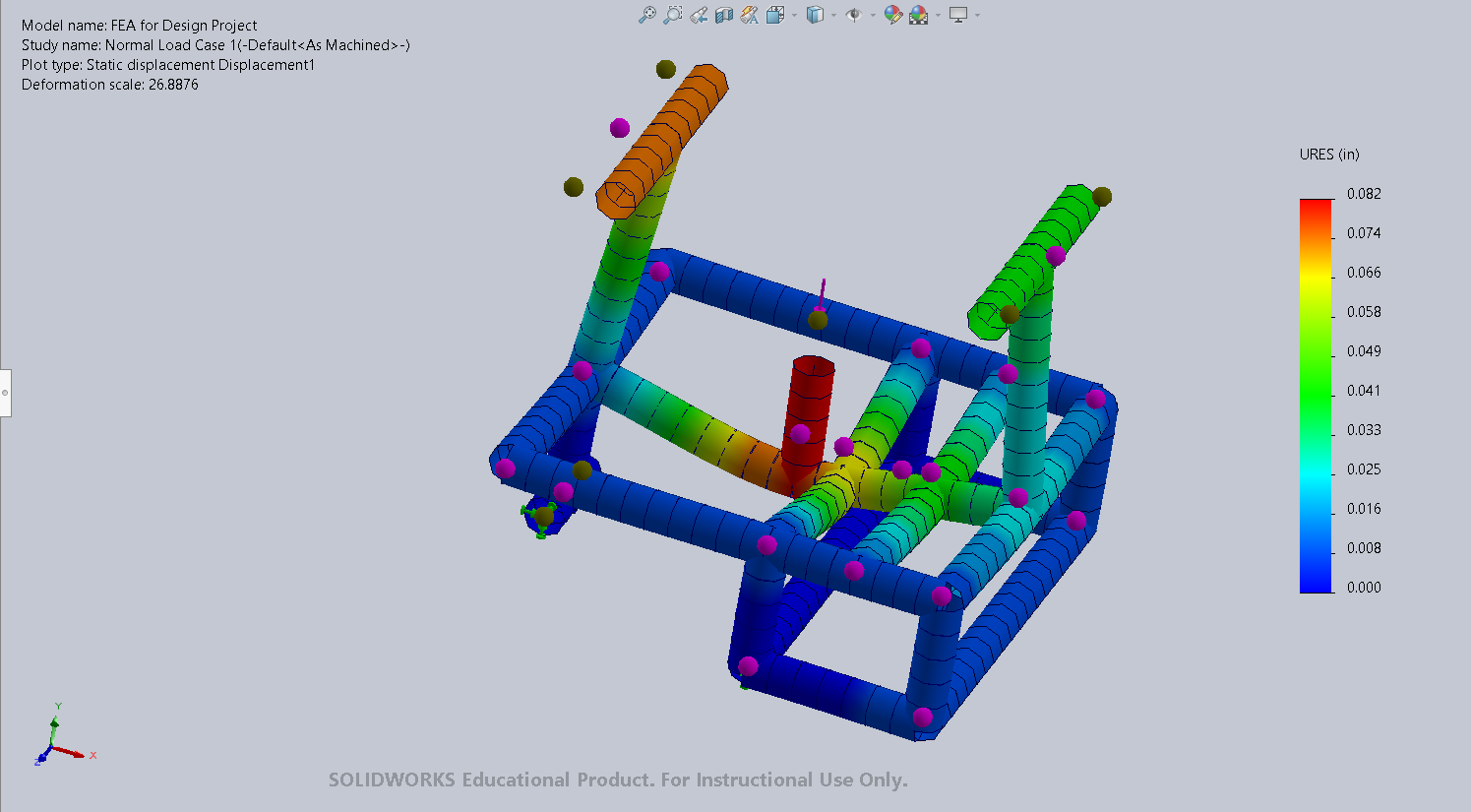
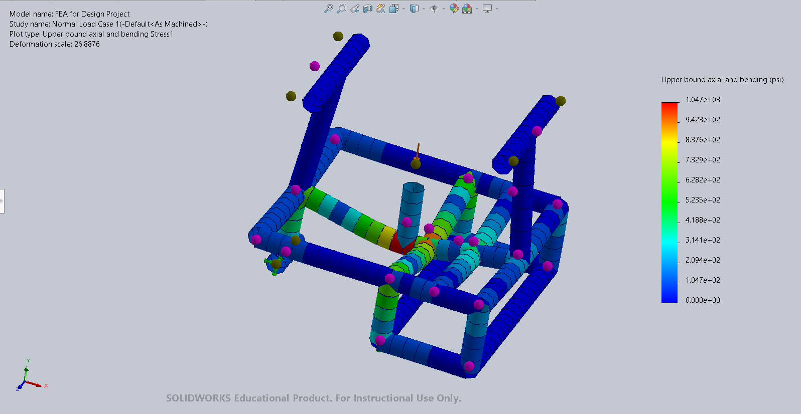
1) Load normal to the cart seat in the vertical plane
The frame was modeled as a weldment and the FEA was modeled using the Beam function. The mesh created was every 1/2" and the normal load was modeled as a point load at the center of seat mount.
The maximum deflection was 0.082 in and the maximum stress was 1047 psi.
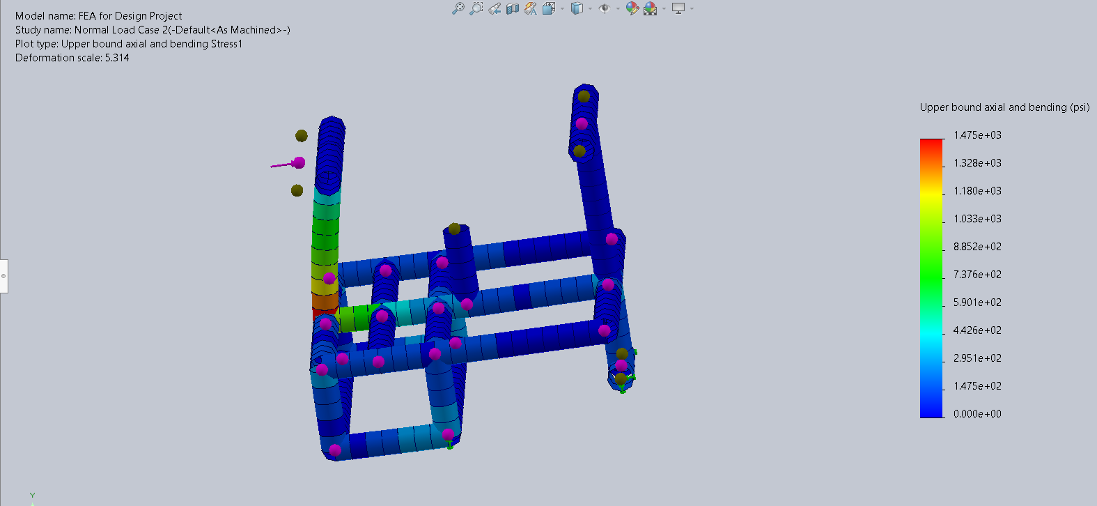
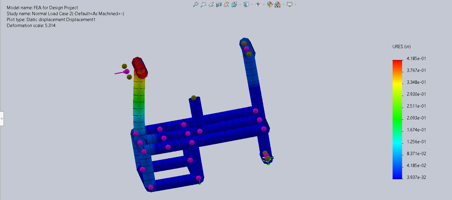
2) Load Normal to the Back Handle bars in the horizontal plane
The frame was modeled as a weldment and the FEA was modeled using the Beam function. The mesh created was every 1/2" and the normal load was modeled as a distributed load across the back handle bars.
The maximum deflection was 0.4185 in and the maximum stress was 1475 psi.
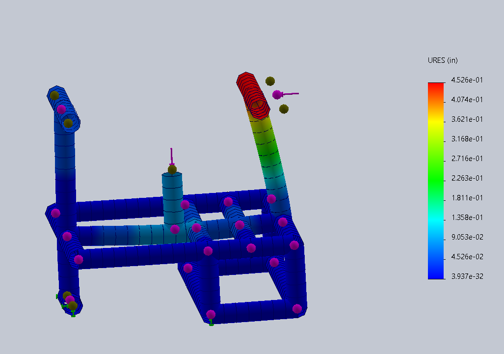
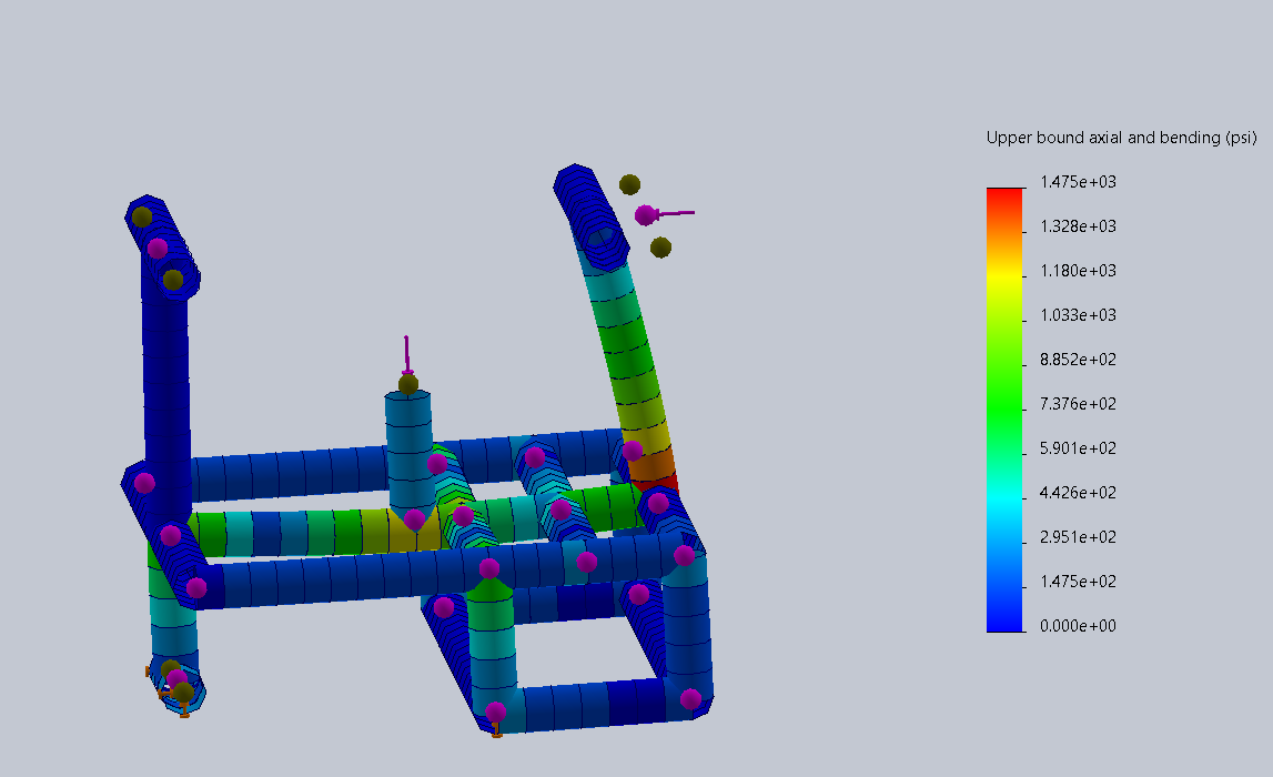
3) Combining 1) and 2) to simulate a person seated on cart while being pushed
The frame was modeled as a weldment and the FEA was modeled using the Beam function. The mesh created was every 1/2" and the normal loads were modeled as a distributed load across the back handle bars and a point load at the center of the seat mount.
The maximum deflection was 0.4526 in and the maximum stress was 1475 psi.
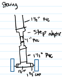

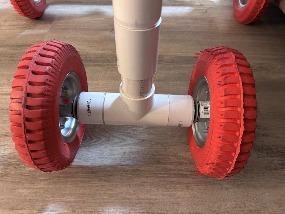
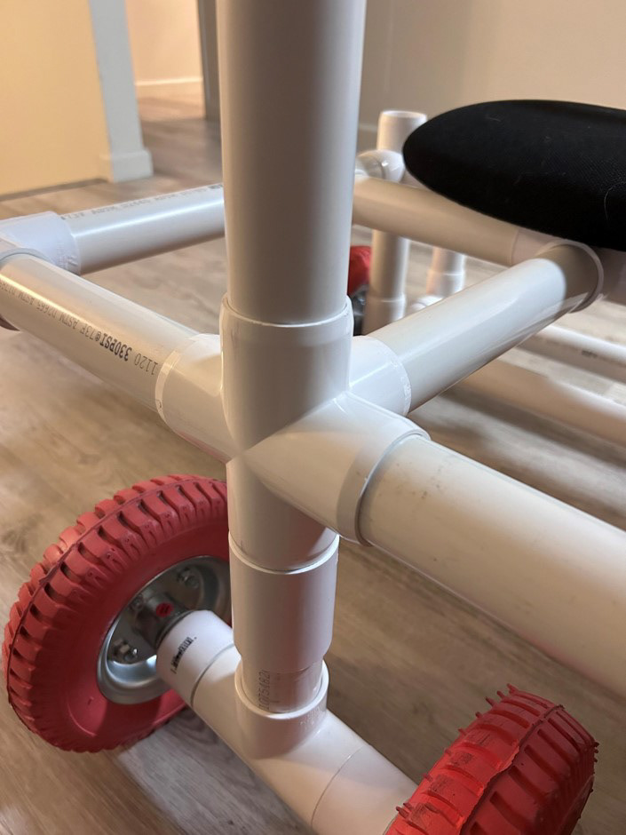
Steering Configuration Design:
We planned to use a 1.5 inch to 1 inch step to be able to use a 1 inch diameter pipe though the PVC connector itself, “the head tube” in bike terms. We then would have put another step adapter to go from the 1 inch to 1.5 inch and set the steering system in place with the wheel and axle system.
Unfortunately, due to the time restriction, we were unable to get the step connectors in time for the build and thus improvised. We bored out the 5 way connector to create a larger inner diameter to allow for a larger slip fit between the steering column and frame. In the future, on top of the step connection, we would also include a bearing in the steering column to minimize friction and allow smoother and more effortless steering.
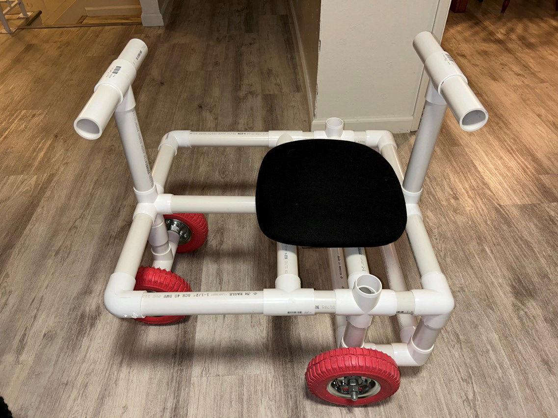
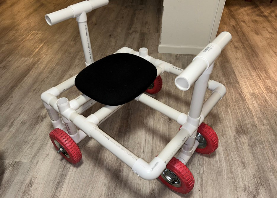
Final Build:
Modifications were made during the build process due to limitations of materials and time. These modifications included the seat, the seat mount, and the steering column.